Tag: temperature

Using bash and gatttool to get readings from Xiaomi Mijia LYWSD03MMC Temperature Humidity sensor

There is a new inexpensive Temperature and humidity sensor by xiaomi.
This time is no longer round ,

Xiaomi Mijia LYWSD03MMC Bluetooth 4.2 Temperature Humidity sensor

if you like me would like to get the temperature and humidity data from time to time to import in a graphing tool like grafana, there is a simple solution using classic bash tools and gatttool.
First you have to indentify the mac-address of your little sensor, for this , just make sure the sensor is in range of your linux device ans launch a
hcitool lescann

this command will spit out all the bluetooth devices in range
just find the line with the name of the device and copy the mac address A4:C1:38:8C:77:CA LYWSD03MMC

then you must start a little bash script like this :

#!/bin/bash
bt=$(timeout 15 gatttool -b A4:C1:38:8C:77:CA --char-write-req --handle='0x0038' --value="0100" --listen)
if [ -z "$bt" ]
then
echo "The reading failed"
else
echo "Got data"
echo $bt temphexa=$(echo $bt | awk -F ' ' '{print $12$11}'| tr [:lower:] [:upper:] )

humhexa=$(echo $bt | awk -F ' ' '{print $13}'| tr [:lower:] [:upper:])
temperature100=$(echo "ibase=16; $temphexa" | bc)
humidity=$(echo "ibase=16; $humhexa" | bc)
echo "scale=2;$temperature100/100"|bc
echo $humidity
fi

this is a skeleton that you can improve , but for now it pretty much work like that ,

first it use gatttol to connect to the sensor and listen for 15 sec
During these fifteen seconds , you can be pretty much sure to receive at least some data like this :

Characteristic value was written successfully Notification handle = 0x0036 value: 58 03 47 a0 0b Notification handle = 0x0036 value: 55 03 47 a0 0b

this tell me that during the 15 sec of connection i received the information that i need two times.
what i’m after are the value 58 03 for the temperature , and 47 for the humidity.

the temperature is little endian format its mean that the two group must be inverted before decoding the data. i invert the values with awk and decode them using bc.
bc doesn’t like when the hex values are not capitalised so tr is used to do that.

bc then give you the temperature multiplied by 100. relaunch bc to divice per 100,

For the humidity its simpler , you get the value in one step without inverting anyting

Then you can do what you need with theses two vars , insert then in some database etc ..

there is room from improvement: for example this script is not capable of decoding negative temperature.
i will post an improved version when i figure out how to do it
Orange pi zero – the battle against HEAT

As you know if you own the orange pi zero, the board run very hot. Running it without an heat sink is not really possible if your board is doing anything other than idling

and even with an heatsink you will encounter throttling if your application is a little intensive.

In an other article I managed to get a fan running controlled by the gpio’s.

A cron check every minute the cpu temperature, if it’s above a set temperature, the fan turn on.

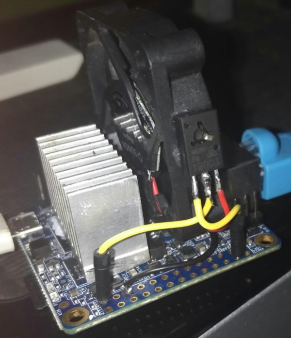
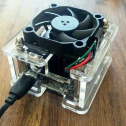
On this photo you can see the NPN transistor fixed to the fan


If it’s under, the fan turns off.

The first time I did that project it was on my first orange pi zero. I made some mistakes in my wiring and, because of that, the fan only received 2.5v, it was spinning very slowly, and I was obliged to do some bash trickery to get the fan to start.

My original orangepi zero was lost during an apartment change.

I decided to order a new one and this time, I wanted to do the best work I could to integrate the fan and heatsink.

I found an acrylic case for the orange pi zero on aliexpress.

And after receiving my orange pi zero, I saw the board was a new revision, it was running even hotter than my previous orange pi zero.

Few days after receiving the board, the case arrived. It was very pretty but it was blocking any air circulation. And the heatsink had no medium to dissipate the heat since the air was hot and not circulating around the metal.
The CPU temperature rapidly ascended to 80°c.

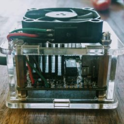
I own several old fans disassembled from old graphics card, and one of the small fans was just the perfect size. I cut a circular hole in the top acrylic plate so the air from the fan could enter and go trough the radiator fins. The air should after exit from a void in a face of the case were optional usb port are placed.

How to use that fan?

The problem with gpio’s is that they only push very weak current and volts (3.3v). You cannot run a fan directly from a gpio.

But you can use a gpio to control an electronic switch (a transistor) that will be able to run the fan

You should use a npn transistor. They are the most common and cost next to nothing. You will find them for free when you tear down old broken power supply.

To turn on and off your switch, you just have to send 1 or 0 on it’s base.

A great way to control the gpio’s of the opi zero is with the help of that library called WiringPI

you will find instructions on how to install the library on the github page.

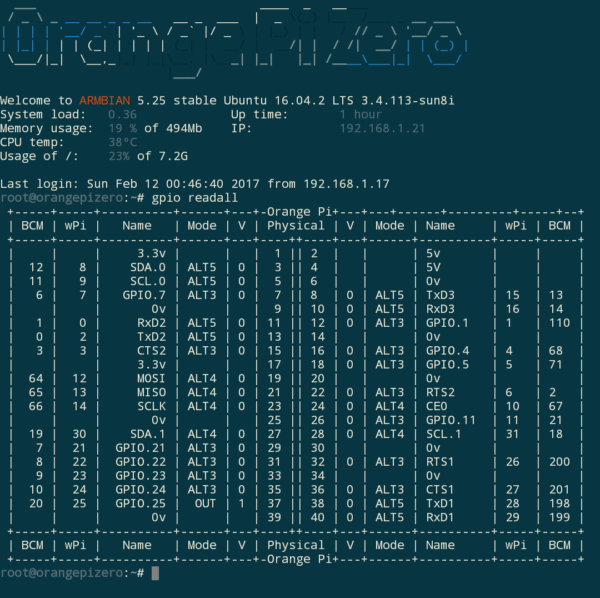
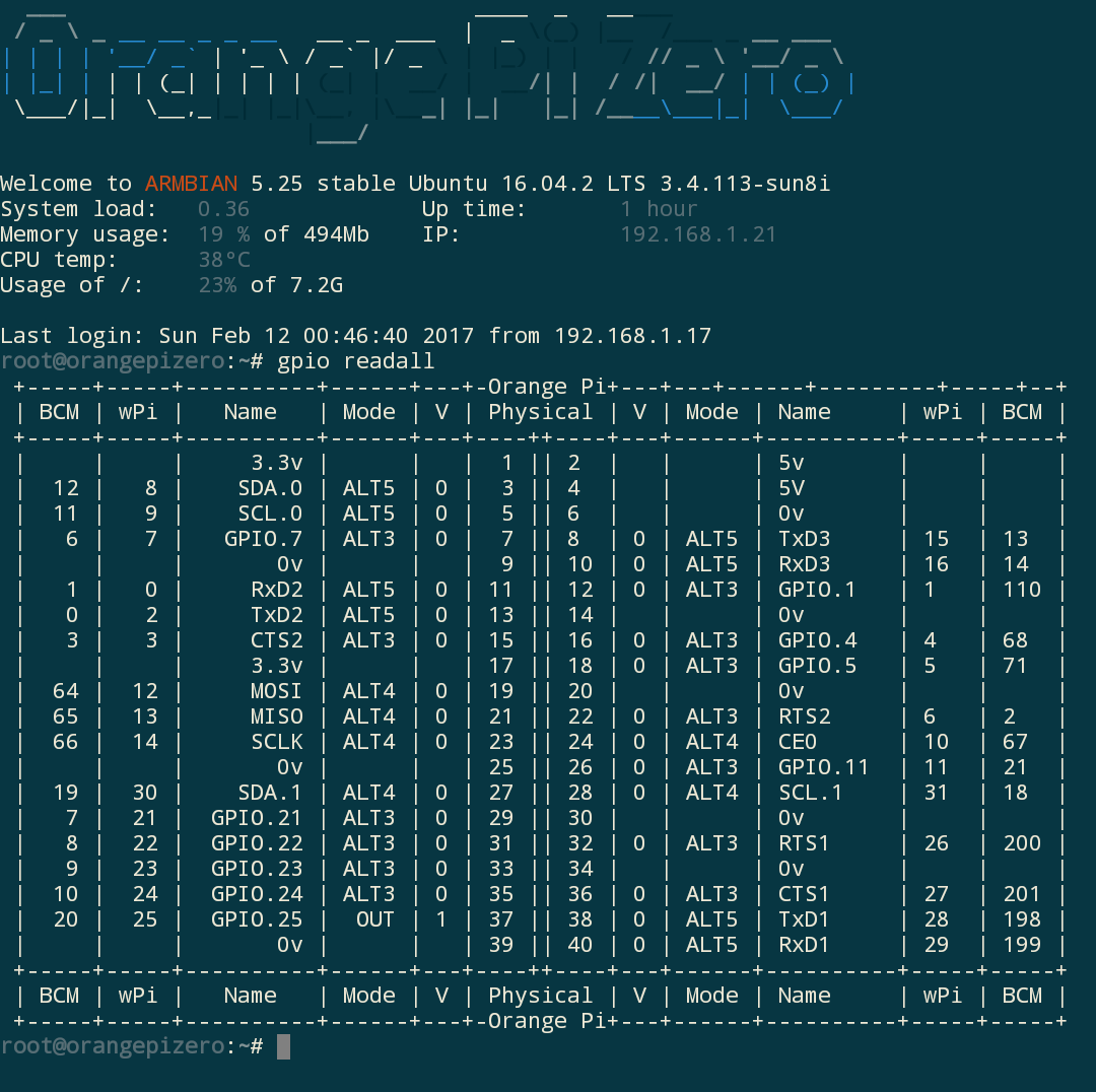
after installation lauch the command gpio readall


i chose the gpio.7 to control my fan ,

conveniently the gpio 7 is placed in the 7th place on the board , and his wPi alias is also 7

as you can see in the attached capture it’s not always the case !


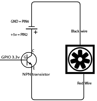
i then solder my fan and transistor following this diagram :

To continue , i must write a script that check for the cpu temperature , and activate the fan if the cpu temperature is above a certain set threshold.

then , using crontab , set this script to launch every minutes.
add the line * * * * * /root/fan-control.sh to your cron jobs , using the command crontab -e

thanks to this script your fan should automatically launch when your Orange is charged , and stop when it’s return to idling.

Control the orange pi zero GPIO

THIS POST HAS BEEN UPDATED


After installing my orange pi zero. I tried to use my board the reencode some video file that use xvid/ac3 to x264/aac with the ffmpeg linux command.

The problem was that it took more than two hours at 100% cpu usage on the 4 cores to reencode the video, during that time the cpu was getting instantly too hot and, as a result, was heavily throttling . I tried to use a radiator, and it significantly reduced the amount of throttling but it was not eliminating it, since eventually the cpu reached pretty high temperature.

I decided to add a fan to blow on the radiator to reduce even further the cpu temperature.

I didn’t want the fan to be running all the time so I decided to use the gpio function of my board to control the state of a pin to start and stop a fan.

The problem is that the logic levels sent by the gpio is 3.3v which is much to low to start the fan i own.

My fan is a 12v fan, but it turns out that it can run at 5v, it just have a lot of trouble starting, most of the time when I put 5 v on the fan, I just see a very small movement, and then nothing, I just have to give a little push, and then it will start

Of course, this is not going to be OK. I must find a way to start that fan without that initial push.

To send 5v instead of 3.3v to the fan I used a PNP transistor that will be controlled by the 3.3v signal.

On this photo , the GPIO control pin is wired to PIN number 23 , after i took that picture i changed it to pin number 7


As you can see on the photo, the pin one of the PNP transistor is wired to a GPIO pin, the pin 2 is wired to the pin 2 of the board which provide constant 5v,and then the pin 3 is wired to the the red wire of the fan.
The black fan wire is connected to the pin number 6 of the board.

Here is a little schematic of the wiring.

To control the gpio I used wiringpi program that I found at this URL

At first I tried to use the gpio pin number 23 but, for some reason I failed to change the state of that pin using the wiring pi library.

I then chosed to use the pin number 7 which is named GPIO.7 in the “gpio readall” command.

First I configured the pin 7 as an output using that command

gpio mode 7 out

Then i use that command to set pin 7 at logic level 1 (3.3v)

gpio write 7 1

But even with all that, my fan still needed a little push to start turning.

After a good afternoon where I considered buying a cheap and small 5v fan on one of the classic Chinese website, i remarked that if my control GPIO pin was not soldered and I disconnected and reconnected very rapidly the control wire, the fan was starting every time.

The idea of a bash script exploiting this fact was born.

Here is the script that works for me every time!

#!/bin/bash

gpio mode 7 out
i=0
while (($i < 10))
do
gpio write 7 1
sleep .1
gpio write 7 0
sleep .05
i=$(($i+1))
echo $i
done

gpio write 7 1

This  script put the pin 7 in output mode, then switch the state of pin 7 rapidly provoking the startup of the fan.  At the end of the script the pin 7 is left in the 1 state.

To be sure the fan started, I usually launch this script 3 times, but it’s overkill and one time is enough most of the time.

When I want to stop the fan, I just launch the command

gpio write 7 0

And the fan stop immediately,

Now creating a script that launch automatically the fan when the cpu get above a predefined temperature is going to be extremely easy, I will describe it in another article.

Even if the fan is turning very very slowly , it does have a very significant effect on cpu temperature

Reduction of more than 10 degrees

Orange Pi Zero : How to get the CPU temperature

If you purchased the small yet awesome orange pi zero on Aliexpress you certainly had huge problems to download some OS images on the official Orange PI website ,

you can download an image on the armbian website that’s compatible with the Orange pi zero

when your orange pi zero is finally fonctional there is several way to get the current temperature of the CPU.

first you can use the command : armbianmonitor -m this command is going to give you , the uptime , cpu speed and the current CPU temperature every 6 seconds.


but if you want to get that temperature for graphing purpose for cacti , munin , or grafana this command is not going to be usefull because of the autorefresh functionality

there is an other command that just return the cpu temperature

cat /sys/devices/virtual/thermal/thermal_zone1/temp 

OR

cat /sys/devices/virtual/thermal/thermal_zone0/temp

there is two sensor inside the Allwinner H2+ , you can add the two values and then divide the result by two to get an average temperature.

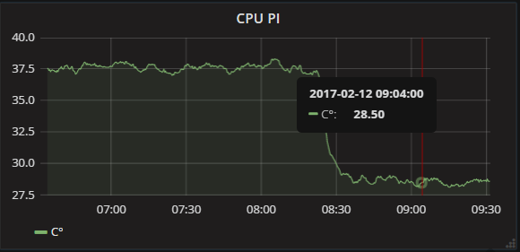
then you can graph the temperature using grafana for example

now that you know the temperature of your PI , you can somthing about it :
in an other article i talk about using the GPIOs of the PI to activate a fan when the temperature reach a set threshold.